|
So much publicity
has been attracted by both the famous four-cylinder
Bentleys, by reason of the niche which they carved for
themselves in the annals of motoring sport during the
1920s, that it is not easy to write an article capable
of doing justice to that rather more dignified big brother,
the 6 1/2-litre "Big Six," which was outstanding
among the cars of nearly twenty years ago.
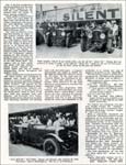
Dignified-yes-but let us not forget that it was one
of these models which, in the hands of those immortal
drivers "Babe" Barnato and "Tim"
Birkin, set the final seals on the racing career of
the Bentley in those memorable years at Le Mans in 1929
and 1930.
Readers of this journal will not need to be reminded
of the more recent achievements of the 6 1/2-litre in
the hands of enthusiasts, and future successes will
doubtless be chronicled as they arise.
This article was planned three years ago as the third
in a series on Bentleys, and it is hoped that it will
prove a worthy successor to those on the 3-litre and
4 1/2-litre which have already appeared in MOTOR SPORT.
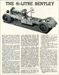
As early as 1925 it became apparent to the designer
of the, by then, world-famous 3-litre, that an entirely
different type of car was required, to meet the needs
of a different class of motorist. Such a car should
have the attributes of a highspeed touring chassis,
should be capable of carrying the enclosed coachwork
of the time, and should handle like a dignified town-carriage.
The development of such a car was no mean task and "W.O",
ably assisted by the redoubtable "K.M.", set
about designing a prototype based on their experience
with the 3-litre. The six-cylinder evolved closely followed
the well-tried layout of the 3-litre, but incorporated
several new features, of which the more important were:
* Six-cylinder engine, 80-mm. bore by 140-mm stroke.
* Coupling-rod-driven overhead camshaft.
* Redesigned frame to carry coachwork of more generous
proportions.
* Redesigned rear axle gear-case to take a new range
of rear axle ratios.
* Gearbox with different ratios to suit this class of
car.
* Redesigned steering assembly.
* As far as is known it was the first motorcar engine
to be flexibly mounted on rubber blocks.
(The mathematically-minded will have observed that this
first "6 1/2-litre" was indeed a 4 1/2-litre!)
Experimental work proved the necessity for various alterations
and culminated in the adoption of a 100-mm. bore 6 1/2-litre
engine as the standard power unit. The increase in engine
size was not entirely unconnected with an unpremeditated
"dice", in France, between the prototype and
the first experimental "Phantom I" Rolls-Royce,
in which "The Sun"-for that is the name under
which the first Bentley Six was registered -had too
little in hand for the liking of "W.O.", who
was driving at the time. The 6 1/2-litre engine developed
140 b.h.p. at 3,500 r.p.m., and its excellent power
output at low r.p.m. met the demands likely to be made
upon a chassis designed for the dual role of town carriage
and high-speed touring car.
The specification of the first production models was
as follows :
Engine. —Six-cylinder, 100-mm bore by 140-mm
stroke, 6,597 c.c.
Four overhead valves per cylinder.
Coupling-rod-driven overhead camshaft.
Compression ratio: 4.4 to 1
Duralumin rockers. Ball-end tappet screws.
Dual ignition by two magnetos.
Thermostatically-controlled water circulation.
Celeron reduction gears, 30 by 60T.
Autovac fuel feed. Single Smith Type 50BVS./C. carburetter.
Clutch. — Single-plate type, Halo lined.
Single-plate clutch-stop.
Gearbox. — B.S. type. Indirect ratios: 3rd,
1.278; 2nd, 1.823; 1st and reverse, 3.364.
Steering. — Worm and sector type.
Rear axle. — Spiral bevel gears, ratio 4.16
to 1.
General. — Wheelbase 11 ft. and 12 ft. 33
in. by 6.75-in. tyres; 21-in. rims. 19-gallon petrol
tank. "Telegauge" petrol gauge. Smith double-pole
lighting and starting.
Road speed at 3,500 r.p.m. = 84m.p.h.
Chassis price, £1,450.
The first models had a half engine-speed dynamo, driven
from the camshaft and located on the aluminium bulkhead
as in the 3-litre, but the majority of these chassis
were later modified to the engine-speed dynamo driven
from the nose of the crankshaft, the radiator shell
being altered to suit. Few, if any, of the original
radiator shells are in existence today.
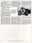
At this point it is convenient to deal with some aspects
of the operation of that somewhat complicated, but nevertheless
reliable type of camshaft drive, the coupling-rod crank-drive-frequently
referred to incorrectly as the "eccentric drive."
Broadly, the system consists of a helical gear-driven,
three-throw crankshaft, having the crank throws at 120
deg., to which are coupled three specially-designed
connecting-rods, which in turn are connected to a driven
crankshaft of similar dimensions direct coupled to the
over-head camshaft. The upper big-end bearings of these
connecting rods are fitted with an expansion-compensating
device to counteract changes in crankpin centres due
to temperature variations, and it is this device at
the camshaft end of the coupling rods, which appears
so complicated to the uninitiated. In the early production
models the device comprised four heavy, square-section
coil springs per coupling-rod, two on either side of
each big-end bearing, so adjusted, by means of suitable
spacing-washers and spring pressures, as to allow automatic
self-adjustment of the centres of the connecting-rod
bearings to suit the alterations in the centres of the
driving and driven crankshafts, as the direct result
of any expansion or contraction caused by temperature
variations in the engine unit. The actual dimensional
centre variations are comparatively small, being of
the order of from 0.016 in. to 0.018 in.
It was soon found that these heavy coil springs were
prone to fatigue fracture under certain engine running-conditions
(periodicity) and, although the number of failures was
small, they were replaced by a novel substitute known
as the " washer drive." This washer-drive
substitute for the spring drive consisted of a tubular
steel spool upon which were assembled forty-nine 25-s.w.g.
(0.020 in.) spring steel washers, each assembly being
dimensionally the same as the coil spring it replaced.
The successful operation of this washer assembly depended
upon the slight " dish " in the thin spring-steel
washers, plus the oil-film between each of the washers,
for the necessary spring pressures to compensate for
the centre variations. In practice these washer-drive
units, once correctly adjusted, remained constant dimensionally
for practically the life of the car.
The setting of these drive unit coupling-rods is a simple
operation requiring two ground mandrels 4 in. in length,
the diameters of which are ground parallel to suit the
bores of the connecting-rods (i.e., the driving and
driven crankshaft diameters), and a V-footed vernier
measuring-rig for measuring between the top diameters
of the centre driving crank-pin and the underside of
the centre driven crank-pin with both crankshafts on
top centre.
The Celeron reduction gear having been correctly meshed,
the centres of the crank-pins of the driving and driven
crankshafts are measured with the vernier. The two mandrels
are now inserted into one of the coupling-rod big-end
bearing assemblies and the centres for the crank-pins
checked, and so adjusted by means of spacing washers
under the bottom pair of washer-drive units as to give
the crankshaft centre dimension plus 0.018 in. with
the assembly "tightened down" on to a 0.022-in.
erecting shim under each washer-drive. The bearing securing-studs
are then filed flush with the top of each securing-nut
and are stamped with an "O" half of which
is on the stud and half of which is on the nut, to ensure
correct assembly. The connecting-rod assembly is then
stripped down and the 0.022-in. erecting shim removed,
thus giving the necessary controlled float (0.022 in.)
to the top big-end bearing to allow for crank-pin centre
variations when the final assembly of the drive is made.
The remaining two connecting-rods are adjusted in a
similar manner.
Due allowance was made in the design of the reduction
gear assembly for any gear-meshing adjustments by the
incorporation of eccentrically-machined bearing bushes
in the driving crankshaft bearing design. These bushes
are flanged; the flanges are slotted and the slots are
numbered for reference purposes and are locked by a
steel-tab extension from the bearing-cap housing. The
movement of these bearings from one slot position to
the next moves the camshaft driving crank approximately
0.005 in. into or out of mesh, according to the direction
of rotation of the bushings. The total slot movements
are:
From 0 to 1, zero ; from 1 to 2, 0.004 in.
From 1 to 3, 0.009 in.; from 1 to 4, 0.014 in.
From 1 to 5, 0.020 in.; from 1 to 6, 0.026 in.
From 1 to 7, 0.031 in.; from 1 to 8, 0.035 in.
From 1 to 9, 0.039 in.; or one millimetre travel from
minimum to maximum.
Another development introduced with the advent of the
6 1/2-litre was the ball-ended tappet screw, designed
to give 100 per cent valve-tip contact with the tappet-adjuster
screw, despite the use of overhead rockers, thus eliminating
the centre-punch effect of the orthodox tappet-screw
on the valve stem face, and, by so doing, reducing the
need for tappet adjustment to very infrequent intervals.
These ball-ended tappet-adjuster screws have, however,
one vice which presents little difficulty to those with
the " know how." If used in an inadequately
vented closed valve-chest they sometimes develop a squeak
or " stick " slightly when the car has stood
idle for a week or so. This trouble is due to the formation
of rust between the ball and socket and can be eliminated
by the introduction of a small quantity of paraffin
into the offending hollow tappet-screw.
Another refinement used for the first time as standard
equipment was the crankshaft torsional damper of the
conventional multi-disc type. Fitted to the front end
of the crankshaft, this self-contained unit, when adjusted
to slip at 60 to 80 foot-pounds, required attention
only at infrequent intervals.
A thermostatically-controlled cooling circuit of unconventional
design completed the layout of this very efficient power
unit. It consisted of two distinct water circulation
circuits regulated by a thermostatically-controlled
valve of ample proportions. In the " cold-engine
" circuit the thermostat by-passed the radiator
except for a small leakage to prevent freezing-up. With
the engine hot, the valve in the open position allowed
the coolant access to the radiator. The whole system
of cylinder block circuits was concealed within the
cylinder block and the front cylinder-block jacket-plate.
The single Smith 5-jet Type 50 BVS/C carburetter supplied
the mixture to a water-jacketed induction pipe of the
"Ram's Horn" balanced-flow type. In view of
the frequent queries raised concerning correct jet sizes
and positions in the jet-platform, perhaps a few words
on this subject would not be out of place.
The 5-jet Smith carburetter consists of an orthodox
float chamber and float mechanism feeding a jet platform,
in which are drilled and tapped five holes to take the
five screw-in " pedestal" jets ; i.e., four
power jets and one slow-running well-jet. This jet carrier
is secured to the base of the carburetter, the four
power-jets projecting into the port block choke or ports.
The port block, cylindrical in form, projects into the
body of the carburetter proper, its flanged base being
secured to the carburetter base, forming the joint cover
of the slow-running annulus machined in the carburetter
base fed by the slow-running tube and the fifth, or
well, jet. Mounted on a cylindrical bronze guide, a
streamlined air valve slides over the machined cylindrical
extension of the port block. This air valve is suction-operated
by the depression in the induction pipe, and governs
the mixture supply and strength according to engine
demands by opening and closing the port openings in
the port block leading from the chokes in the base of
the port block.
As these chokes or ports are of varying sizes, the jets
are of necessity of various sizes, and it is of paramount
importance that the correct size jet is fitted to the
correctly numbered jet orifice in the jet platform.
The jet sizes are: Well, 40/45; No. I, 50/65; No. 2,
140; No. 3, 120/130; No. 4, 85/115.
A starting device or strangler and a mixture control
is incorporated in the design and consists of a cam-operated
sleeve sliding over the well jet which, in the "
full rich " position, closes the air supply to
the well jet, and in the " full weak " position,
opens a series of holes in the base of the port block.
This carburetter is very reliable and, apart from choked
jets, the only troubles likely to occur are : (a) air
valve inclined to stick or become sluggish in action,
and (b) slow-running annulus choked or orifice masked
by new joint.
The steering-box, of the orthodox semi-reversible worm
and segment type, was of entirely new design incorporating
a meshing arrangement consisting of an eccentrically
- machined, slotted - sleeve bearing for the segment
shaft. After removing the securing tab and slackening
off the sleeve pinch-bolt, the rotation of this sleeve
moved the segment into or out of mesh, according to
the direction of rotation. End float was adjusted by
the method common to all Bentley chassis, viz., the
steel sleeve with inclined slots secured by two pinch-bolts
at the base of the box casting.
As in the 3-litre, the brakes were fully mechanically
operated, but the front brakes were " push-rod"
operated in order to utilize the considerable self-energisation
developed by the torsional effect of the brakes on the
front axle assembly. The method was a phase in the development
of the " reversed action " front brakes used
so effectively at Le Mans.
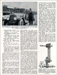
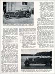
The first 6 1/2-litre chassis (WB 2551) took the road
in March, 1926. In frontal appearance it differed slightly
from later models by reason of the absence of the casing
carrying the engine-speed dynamo driven from the crankshaft,
as the dynamo was camshaft-driven at the rear end of
the engine.
One of the first modifications was the introduction
of the long-range E.R.6 magneto to cope with the extra
flexibility demanded from the engine by town- running
conditions.
Clutch judder evidenced itself in those cars used chiefly
for town work and at first the use of first engagement
cork inserts was tried effectively, until the advent
of the spring-loaded pressure plate at chassis No. DH
2204 in February, 1927.
The drain on batteries resulting from starting an engine
of this capacity coupled with the difficulty in keeping
batteries in a fully-charged condition on cars used
solely for town work led to the fitting of Ki-gass injectors
to all chassis and the development of the five-brush,
crankshaft-driven dynamo referred to earlier. The first
chassis with the re-designed radiator allowing for this
dynamo, the casing of which was secured to the front
engine-bearer, appeared at the 1927 Motor Show. The
radiator with its fuller profile and deeper (100 mm.
section) matrix greatly enhanced the frontal aspect
and was to remain a distinguishing feature throughout
the 6 1/2-litre's career.
Other modifications incorporated in the 1927 Show model,
and introduced as standard from chassis No. KD 2121,
included a torsional camshaft damper to replace the
damping effect of the camshaft-driven dynamo ; coil
ignition for the first time as a standard fitment to
Bent-leys ; the enclosed-joint, balanced propeller shaft
(soon to become known as the Hardy-Spicer shaft) in
place of the open shaft and plunging joint used hitherto;
and Dewandre servo brakes. These chassis had an enthusiastic
reception from discerning motorists and development
work proceeded apace. A magneto anti-vibrator was added
at chassis No. MD 2649 and single-pole wiring at chassis
No. FA 2514. At the same time the camshaft oilbath was
introduced to prevent" rocker roller pick-up,"
a modification which proved to be the most effective
as yet produced to overcome this spasmodic trouble.
About this time (September, 1928) rumours were afoot
that there was every possibility that a "Speed
Model" of this chassis had been scheduled for development
and early production. Much development work was, in
fact, proceeding behind the scenes and culminated in
the production of an entirely new type of chassis to
be known as the " Speed Six." The first of
these chassis to be laid down was chassis No. WT 2265
and the principal alterations in design were as follows:
High-compression pistons, giving 5.3 to 1 compression-ratio.
Twin S.U. carburetters. BM 7032 camshaft. 0.019 in.
tappet clearance.
"C"-type gearbox with indirect ratios -3rd,
1.357 to 1; 2nd, 1.823 to 1; 1st and reverse, 3.364
to 1.
3.84 to 1 rear axle ratio.
(BM 7055 camshaft with 0.006 in. tappet clearance was
available as an alternative to BM 7032 for use with
closed coachwork.)
The radiator was redesigned-the sides were parallel
whereas the "standard" 6 1/2-litre radiator
had a pronounced taper inwards at the bottom-and the
"winged-B" had a green label.
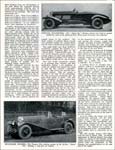
From a commercial standpoint the "Speed Six"
development had to include exploration of the probabilities
and possibilities of this car superseding the now hard-pressed
4 1/2-litre in the competition field. Intensive development
work was carried out unobtrusively. Air flow tests were
made, the cylinder block was redesigned, port areas
were altered, and brake endurance tests were carried
out.
Eventually the first Le Mans-type "Speed Six"
chassis No. LB 2332, took the road and as its preliminary
try-out ran in the "Double-Twelve" race at
Brooklands in May, 1929. Although ill-luck dogged the
chassis premiere, the dynamo coupling disintegrating
when victory seemed assured, the general performance
exceeded all expectations.
The brief specification of the first " Le Mans
Speed Six " chassis was as follows:
Engine — Hour-glass pistons, 5.8 to 1 compression-ratio.
BM 7032 camshaft. Single-port cylinder block. Flat type
inlet valves. Five-gallon sump. Large capacity oil pump.
Increased oil feed to main and big-end bearings. Heavy-section,
direct-metalled connecting rods. "Mintex"
crankshaft torsional damper. Twin S.U. carburetters,
Type HVG5. Straight-toothed metal reduction gears.
Clutch — Single plate. Steel pressure plate.
Reinforced clutch stop.
Gearbox — "D" type. Indirect ratios
- 3rd, 1.33 to 1; 2nd, 1.63 to 1; 1st and reverse, 2.64
to 1.
Rear axle — Straight-toothed bevels. (16/48=3
to 1 ratio.)
Brakes — Standard.
General — Wheelbase lift. 6 in. 32-in. by
6 in. road-racing tyres. 45-gallon petrol tank. Autopulse
petrol feed. Duplex fuel lines. Smith five-brush dynamo.
4LSA starter motor. Lucas lamps. Young 84-amp. hour-capacity
battery.
The "Speed Six" entered the lists of competition
in 1929 and immediately combined with its four-cylinder
stable companions to set England's star higher in the
firmament of international motor racing than ever before
or, alas, since.
On May 10th, the car which was afterwards to be dubbed
"Old No. 1" came to the starting line for
the " Double-Twelve" at Brooklands. It was
driven by "Babe" Barnato and J. D. Benjafield,
bore the number 2 and, after an excellent performance
during which several laps in the region of 92 m.p.h.
were completed, retired owing to a fracture in the dynamo-drive.
The 24-hour race at Le Mans that year needs little recapitulation
to any enthusiast, for Bentleys filled the first four
places and nobody else had a look in. No. 1 "Speed
Six" more than made amends for her failure in the
"Double-Twelve" by winning the race, in the
experienced hands of Woolf Barnato and "Tim"
Birkin. She averaged 73.63 m.p.h., covered 1,767 miles
in the process and, just for good measure, gained the
Rudge Cup as well. It was the first occasion upon which
the winner of the Grand Prix d'Endurance had also carried
off this cup.
It is most interesting to read the contemporary report
of Mr. Clarke on this chassis:
(a) During practic: Slight steering-instability
reported and rectified by balancing the practice wheels
and adjusting shock-dampers. Oil pressure-60 lbs.
(b) During race: Brake adjustment-used up at
the 20th hour.
(c) After race: (strip report)
Engine: Nothing to report. Exhaust valves and
valve springs changed as a precautionary measure only.
Clutch; Nothing to report. Clutch-stop locating
ears fractured.
Gearbox: Nothing to report. Main-shaft, first
motion shaft and journal bearings changed as a precautionary
measure.
Rear axle: Crown-wheel and pinion -slight signs
of pitting, otherwise O.K. Pinion thrust-race disintegrated.
Otherwise O.K.
Brakes: Relined: Two rear drums changed as a
precautionary measure (local hot spot).
Frame: Small fracture through front engine bearer
engine securing bolt hole. Signs of fracture where front
wing stay palms connected to neutral section of frame
channel due to 'fidgeting.'
Truly a remarkable strip report after a gruelling race
of this calibre.
On the 29th of the same month, "Old No. 1"
was back again at Brooklands for the Six-Hour Race,
still driven by " Babe," but this time with
Jack Dunfee as co-driver. It bore the number 3 and again
won, averaging 75.88 m.p.h. for the race.
On July 13th, Glen Kidston took the big Bentley over
to Phoenix Park for the Irish Grand Prix and came in
2nd behind Ivanovski's Alfa-Romeo. Its speed was 79.80
m.p.h.
The T.T. that August broke, temporarily, the big car's
run of success, for, in company with Glen Kidston, it
ran out of road at Bradshaw's Brae and was too badly
damaged to continue. Its race number, incidentally,
was 73.
The final event in "Old No. 1's" 1929 season
was the classic 500-Mile Race at Brooklands. It had
a special two-seater body with a short, stubby tail,
was driven by Sammy Davis and Clive Dunfee, and came
2nd, averaging 109.40 m.p.h.
Following the racing successes of 1929, the cars at
the 1929 Show incorporated the following modifications
(in the KR-series chassis):
Single-port cylinder block. 5.3 to 1 compression-ratio.
BM 7055 camshaft. Bosch magnetos. Shell-type connecting-rods.
38.4 to 1 rear axle ratio. Electron steering box and
rear axle casing.
At chassis No. LR 2783 the three-quarter engine speed
magneto and coil ignition became standard.
Le Mans in 1930 was to see the final appearance of the
"works" team of Bent-leys and the cars were,
for all practical purposes, identical mechanically with
those of the previous year with the following exceptions:
Engine — 6.1 to 1 compression-ratio. Three-quarter
engine speed magneto and coil ignition. Shell-type connecting-rods.
Clutch — Reinforced clutch stop.
Rear axle — 15/47 gears=3.13 to 1.
In this last season of the Bentley team the " Big
Sixes " acquitted themselves gloriously indeed.
Two of them were entered for the "Double-Twelve"
on May 9th and 10th, being numbered 2 (Barnato and Clement)
and 3 (Davis and C. Dunfee). In shocking weather conditions
these Bentleys came in 1st and 2nd, respectively, at
86.68 m.p.h. and 85.68 m.p.h. No. 3 gained its place
despite a certain amount of trouble with a seized crankshaft-damper
and some (probably consequent) valve-spring breakage.
Three of the big Bentleys went to the line for the last
Le Mans of all in June, 1930. They were numbered 2,
3 and 4, being driven by Clement and Watney, "Sammy"
Davis and Clive Dunfee, "Babe" Barnato and
Glen Kidston,' and these last two roared past the chequered
flag, 24 hours later, having won the race without in
any way extending their car, at an average of 75.87
m.p.h. This was "Babe's" third consecutive
win at Le Mans. Clement and Watney were 2nd, at 73.33
m.p.h., whilst Dunfee shortly after taking over No.
3 from Davis, had the misfortune to charge the sandbags
on his first bend, sustaining damage which enforced
retirement.
The team, nevertheless, again won the Rudge Cup, in
addition to the entire race.
Such was the way of the closing of the greatest chapter
which any single marque has ever added to the
annals of British motor racing history-and the departure
of the Bentley Team from racing left a gap which has
not since been filled.
Altogether 544 6 1/2-litre Bentleys were made, of which
171 were "Speed Sixes" and, of these, more
than 70 are on the roads to-day in the hands of Bentley
Drivers' Club members, including two of the team cars.
GF 8507 (chassis No. HM 2868) is owned by J. D. Percy
and is in its original form and beautifully kept. It
was this car in which "Babe" Barnato won Le
Mans for the third time and, fittingly, it led his funeral
cortege bearing floral tributes, driven by "Babe's"
chauffeur. GF 8511 has recently come to light in the
north of England and the ravages of time are being removed.
MT 3464, the "Old No. 1's" winner of Le Mans
in 1929, 2nd in the 1929 "500," and 1st in
that year's Six-Hour Race, continued her wonderful career
until 1931 when she took that fated plunge over the
top of the banking at Brooklands killing Clive Dunfee.
The engine of this car was used for a time in the Barnato-Hassan
before the 8-litre was installed, and other bits were
used in a special 8-litre road car built for "Babe"
Barnato. Its identity has thus been lost.
The modified "Speed Six" used in post-war
competition motoring sport with signal success by Pierre
Marechal is one of the very few short-chassis cars (11
ft. wheelbase) and is thought to have been a spare car
for the "works" team.
So concludes the story of truly one of the giants of
the road, which never fails to impress wherever it appears.
The majesty of the "Speed Six" will continue
for many years to dwarf motor cars of younger vintage,
and the rear view, if not as imposing as the front end,
will frequently impinge itself upon the vision of the
driver of many a modern car who thought that he himself
wasn't exactly hanging about.
|